- Downloads
- Sounds
- projects.esu.eu
- Search results
V60 LokSound 5 factory equipped sounds  H0 N XL L M4
- Article numbers:94472
- Last change: 2/5/2021
- Manufacturer: Piko

Zu Beginn der 1950er-Jahre musste die junge Deutsche Bundesbahn (DB) ihre Lokomotivflotte erneuern. Neben Streckenloks kamen auch Rangierloks auf die Reißbretter. Für den leichten Rangierdienst gab es etwa 500 Exemplare der Kleinloks der Typen Kö/Köf. Die modernsten, speziell für den leichten und mittelschweren Verschiebedienst beschafften Einheits-Dampflok-Baureihen BR 80 und 81 waren nur in einer bescheidenen Stückzahl von zusammen 27 Exemplaren vorhanden. Den schweren Rangierdienst übernahmen abgehalfterte Streckenloks der BR 55 und 57 und die wackeren mehrheitlich preußischen BR 94. Dazu kamen aus Wehrmachtsbeständen noch 25 V20 und 70 V36. Da viele Strecken und noch mehr Rangierbahnhöfe noch nicht mit Fahrleitung überspannt waren, tat die Beschaffung einer neuen Diesellok Not.
Nach den guten Erfahrungen mit den dreiachsigen V36, deren Achsen mit Kuppelstangen verbunden waren, stand eine ebenfalls dreiachsige (der besseren Übersicht halber), aber mit einem Mittelführerstand versehene Lok auf dem Wunschzettel der DB.
1953 schlossen sich die Fahrzeughersteller Maschinenbau AG (MaK), Gmeinder, Henschel, Jung, Klöckner-Humboldt-Deutz, Krupp und Maschinenfabrik Esslingen unter Federführung des Bundesbahn-Zentralamt (BZA) München zur Arbeitsgemeinschaft für die Entwicklung der V60-Diesellokomotive der Deutschen Bundesbahn (AGM V60) zusammen.
Die Arbeitsgruppe hatte zunächst ermittelt, dass die Motorleistung zum Bestehen der geforderten Aufgaben ungefähr bei 600 PS liegen müsse, wodurch sich die Bezeichnung V60 ableitet. Im Lastenheft stand eine Lokomotive, mit der der größte Teil des leichten Rangierdienstes abzudecken wäre. Bei den Streckendiesellokomotiven V80 und V200 hatte sich der Gelenkwellenantrieb bewährt, doch aufgrund der mangelnden Erfahrung mit einem dreifach gelagerten Antrieb entschied man sich für das von der V36 bekannte Antriebsprinzip mit Kuppelstangen und Blindwelle.
Das Fahrwerk sollte so ausgelegt sein, dass eine maximale Achslast von 16 Tonnen nicht überschritten wurde, damit die Maschine ihre Arbeit auch auf sich in schlechtem Zustand befindlichen Neben- und Anschlussgleisen verrichten konnte. Als Maximalgeschwindigkeit im Streckengang waren 60 km/h gefordert, womit die Lok genau so schnell war, wie die damals üblichen Durchgangsgüterzüge, und die zulässige Geschwindigkeit auf Nebenstrecken ausnutzte. Auch auf eine narrensichere Bedienung hat der Auftraggeber bestanden. Mit einem Treibraddurchmesser von 1250 mm ergab sich bei 60 km/h eine Radumdrehungszahl von 255 U/min, womit die Entwickler im für Stangenantriebe üblichen Rahmen blieben. Man kann vom heutigen Standpunkt sagen, dass man sich bei der V60 auf keinerlei Experimente eingelassen hatte.
Der ebenfalls zur Ausstattung gehörende kohlegefeuerte Warmhalteofen (Dofa-Ofen) diente nicht zum Vorheizen der Züge, sondern lediglich zum Warmhalten der abgestellten V60. Da die Kohle für den Ofen per Hand eingefüllt werden musste, ging die DB für Loks bis zur dritten Nachbauserie dazu über, ölgefeuerte Sturzbrenner der Firma Hagenuk einzubauen. Da weiterhin der Brennraum des Dofa-Ofens genutzt wurde, lassen sich die Loks mit den unterschiedlichen Warmhaltegeräten äußerlich nicht unterscheiden. Loks ab der 4. Nachbauserie erhielten ab Werk einen ölgefeuerten Warmwasserkessel, der einen runden Querschnitt hat, womit sich die Loks deutlich von den Vorgängerserien unterscheiden.
Ab den 1990er-Jahren ersetzte die DB die Öfen durch mit Fremdstrom betriebene Warmhaltegeräte, wodurch die Öfen am vorderen Ende unterhalb des rechten Umlaufs entfielen. Weitere äußerliche Änderungen waren der Einbau von Indusimagneten ab Mitte der 1960er-Jahre sowie ab 1985 die Ausrüstung der Mehrzahl der Loks mit automatischen Kupplungen. Den fünf ab 1955 gelieferten Vorauslokomotiven folgten verteilt auf fünf Nachbauserien bis April 1964 weitere 937 Maschinen. Die Vorausloks unterscheiden sich sowohl untereinander, als auch von den äußerlich weitgehend identisch ausgeführten Nachbauserien.
DB-intern werden die Serienmaschinen in leichte und schwere Loks unterteilt. Äußerlich unterscheiden sich beide Typen nicht. Die 54 t auf die Waage bringende schwere Ausführung besitzt einen stärker dimensionierten Rahmen als die nur 48 t wiegenden leichten Loks. Zunächst trugen die leichten Loks drei-, die schweren vierstellige Ordnungsnummern. Mit Einführung der computergerechten Bezeichnungen im Jahre 1968 erhielten die leichten Loks die Baureihennummer BR 260, die schweren wurden als BR 261 geführt.
Bis in die frühen 1980er-Jahre mussten die Loks beider Baureihen mit als Lokführer ausgebildetem Personal besetzt werden. Die den Kleinloks zugeteilten Kö-Typen durften dagegen auch von speziell geschultem Rangierpersonal bedient werden, was geringere Personalkosten zur Folge hatte. Durch eine 1987 durchgeführte Umzeichnung der Loks in die Baureihen 360 und 361 teilte die DB die Maschinen den Kleinloks zu und schuf für die als Lokpersonal ausgebildeten Rangierer die Berufsbezeichnung Lok-Rangier-Führer. Die mit Automatischer Kupplung (AK) und Funkfernsteuerung ausgerüsteten Maschinen erhielten die Bezeichnung 364 (leichte Bauart) und 365 (schwere Bauart).
Die BR 362 und 363 entstanden erst ab 1992 und bezeichnen Loks, die mit dem Caterpillar-Motor 3412 DI-TA anstatt des originalen Maybach GTO 6 / GTO 6A ausgerüstet wurden. Andere in einzelnen Loks erprobte Motoren waren stückzahlenmäßig nicht relevant.
Die mittlerweile bei nahezu allen Maschinen fast 50 Jahre betragende Einsatzdauer zeigt, dass es sich bei der V60 um eine glückliche Konstruktion handelt. Laut dem Stand - Sommer 2012 - befinden sich noch 405 Maschinen der Baureihen 360 bis 365 im Bestand der DB, privater Betreiber oder bei Museumsbahnen.
Haupttätigkeitsfeld der V60-Typen war von jeher der Rangierdienst, doch kamen die Loks auch stets mit Übergabezügen rund um den Kirchturm der jeweiligen Bahnbetriebswerke (Bw) zum Einsatz. Mangels Zugheizung waren Einsätze im Personenverkehr sehr selten, da es in diesem Fall einer Zugheizeinrichtung im Personenwagen bedurfte. Trotzdem gab es gerade in den 1960er-Jahren zahlreiche Direktionen, die die V60 vor mit Kohleöfen ausgestattete Donnerbüchsen spannten. Regelmäßige Personenzugeinsätze gab es in den Direktionen Augsburg, Nürnberg, Essen und Wuppertal.
Nach der Wende 1990 hielten die West-V60 auch in den neuen Bundesländern Einzug. Und das, obwohl die DR vierachsige Rangierloks der Baureihen 105 und 106 mit ähnlichen Leistungsdaten im Bestand hatte. So taten in den 1990er-Jahren Loks der BR 364 und 365 in den Regionalbereichen Schwerin (Betriebhof Stralsund, Rostock, Pasewalk, Neustrelitz), Berlin (Bh Berlin-Pankow, Seddin, Cottbus), Erfurt (Bh Erfurt), Halle (Bh Leipzig Süd), Dresden (Bh Dresden, Chemnitz, Reichenbach) ihren Dienst.
Fabrikneu wurden V60 an die belgischen (SNCB-NMBS), griechischen (CEH) sowie an die türkischen Staatsbahnen (TCDD) und nach Israel geliefert. Die zuverlässigen Loks waren nach ihrem Ausscheiden in Deutschland beliebte Exportartikel. So gelangten die Loks in die Schweiz, nach Norwegen, Jugoslawien, Italien und Algerien.
Dieses Projekt ist abgestimmt für die Verwendung von PIKO's V60 (ab Produktionsjahr 2019). AUX-Belegung und Funktionstastenbelegung folgen den PIKO Standards. Schreiben Sie dieses Soundprojekt einfach auf einen LokSound 5 mit PluX22 Schnittstelle. Keine weiteren Einstellungen sind erforderlich. Hide description more…
H0 N XL L M4
- Article numbers
- 94472
- Last change
- 2/5/2021
- Manufacturer
- Piko
V 60 LokSound 5 European Sound files H0 N XL L M4
- Article numbers:S0031
- Last change: 2/5/2021
- Manufacturer: ESU
Zu Beginn der 1950er-Jahre musste die junge Deutsche Bundesbahn (DB) ihre Lokomotivflotte erneuern. Neben Streckenloks kamen auch Rangierloks auf die Reißbretter. Für den leichten Rangierdienst gab es etwa 500 Exemplare der Kleinloks der Typen Kö/Köf. Die modernsten, speziell für den leichten und mittelschweren Verschiebedienst beschafften Einheits-Dampflok-Baureihen BR 80 und 81 waren nur in einer bescheidenen Stückzahl von zusammen 27 Exemplaren vorhanden. Den schweren Rangierdienst übernahmen abgehalfterte Streckenloks der BR 55 und 57 und die wackeren mehrheitlich preußischen BR 94. Dazu kamen aus Wehrmachtsbeständen noch 25 V20 und 70 V36. Da viele Strecken und noch mehr Rangierbahnhöfe noch nicht mit Fahrleitung überspannt waren, tat die Beschaffung einer neuen Diesellok Not.
Nach den guten Erfahrungen mit den dreiachsigen V36, deren Achsen mit Kuppelstangen verbunden waren, stand eine ebenfalls dreiachsige (der besseren Übersicht halber), aber mit einem Mittelführerstand versehene Lok auf dem Wunschzettel der DB.
1953 schlossen sich die Fahrzeughersteller Maschinenbau AG (MaK), Gmeinder, Henschel, Jung, Klöckner-Humboldt-Deutz, Krupp und Maschinenfabrik Esslingen unter Federführung des Bundesbahn-Zentralamt (BZA) München zur Arbeitsgemeinschaft für die Entwicklung der V60-Diesellokomotive der Deutschen Bundesbahn (AGM V60) zusammen.
Die Arbeitsgruppe hatte zunächst ermittelt, dass die Motorleistung zum Bestehen der geforderten Aufgaben ungefähr bei 600 PS liegen müsse, wodurch sich die Bezeichnung V60 ableitet. Im Lastenheft stand eine Lokomotive, mit der der größte Teil des leichten Rangierdienstes abzudecken wäre. Bei den Streckendiesellokomotiven V80 und V200 hatte sich der Gelenkwellenantrieb bewährt, doch aufgrund der mangelnden Erfahrung mit einem dreifach gelagerten Antrieb entschied man sich für das von der V36 bekannte Antriebsprinzip mit Kuppelstangen und Blindwelle.
Das Fahrwerk sollte so ausgelegt sein, dass eine maximale Achslast von 16 Tonnen nicht überschritten wurde, damit die Maschine ihre Arbeit auch auf sich in schlechtem Zustand befindlichen Neben- und Anschlussgleisen verrichten konnte. Als Maximalgeschwindigkeit im Streckengang waren 60 km/h gefordert, womit die Lok genau so schnell war, wie die damals üblichen Durchgangsgüterzüge, und die zulässige Geschwindigkeit auf Nebenstrecken ausnutzte. Auch auf eine narrensichere Bedienung hat der Auftraggeber bestanden. Mit einem Treibraddurchmesser von 1250 mm ergab sich bei 60 km/h eine Radumdrehungszahl von 255 U/min, womit die Entwickler im für Stangenantriebe üblichen Rahmen blieben. Man kann vom heutigen Standpunkt sagen, dass man sich bei der V60 auf keinerlei Experimente eingelassen hatte.
Der ebenfalls zur Ausstattung gehörende kohlegefeuerte Warmhalteofen (Dofa-Ofen) diente nicht zum Vorheizen der Züge, sondern lediglich zum Warmhalten der abgestellten V60. Da die Kohle für den Ofen per Hand eingefüllt werden musste, ging die DB für Loks bis zur dritten Nachbauserie dazu über, ölgefeuerte Sturzbrenner der Firma Hagenuk einzubauen. Da weiterhin der Brennraum des Dofa-Ofens genutzt wurde, lassen sich die Loks mit den unterschiedlichen Warmhaltegeräten äußerlich nicht unterscheiden. Loks ab der 4. Nachbauserie erhielten ab Werk einen ölgefeuerten Warmwasserkessel, der einen runden Querschnitt hat, womit sich die Loks deutlich von den Vorgängerserien unterscheiden.
Ab den 1990er-Jahren ersetzte die DB die Öfen durch mit Fremdstrom betriebene Warmhaltegeräte, wodurch die Öfen am vorderen Ende unterhalb des rechten Umlaufs entfielen. Weitere äußerliche Änderungen waren der Einbau von Indusimagneten ab Mitte der 1960er-Jahre sowie ab 1985 die Ausrüstung der Mehrzahl der Loks mit automatischen Kupplungen. Den fünf ab 1955 gelieferten Vorauslokomotiven folgten verteilt auf fünf Nachbauserien bis April 1964 weitere 937 Maschinen. Die Vorausloks unterscheiden sich sowohl untereinander, als auch von den äußerlich weitgehend identisch ausgeführten Nachbauserien.
DB-intern werden die Serienmaschinen in leichte und schwere Loks unterteilt. Äußerlich unterscheiden sich beide Typen nicht. Die 54 t auf die Waage bringende schwere Ausführung besitzt einen stärker dimensionierten Rahmen als die nur 48 t wiegenden leichten Loks. Zunächst trugen die leichten Loks drei-, die schweren vierstellige Ordnungsnummern. Mit Einführung der computergerechten Bezeichnungen im Jahre 1968 erhielten die leichten Loks die Baureihennummer BR 260, die schweren wurden als BR 261 geführt.
Bis in die frühen 1980er-Jahre mussten die Loks beider Baureihen mit als Lokführer ausgebildetem Personal besetzt werden. Die den Kleinloks zugeteilten Kö-Typen durften dagegen auch von speziell geschultem Rangierpersonal bedient werden, was geringere Personalkosten zur Folge hatte. Durch eine 1987 durchgeführte Umzeichnung der Loks in die Baureihen 360 und 361 teilte die DB die Maschinen den Kleinloks zu und schuf für die als Lokpersonal ausgebildeten Rangierer die Berufsbezeichnung Lok-Rangier-Führer. Die mit Automatischer Kupplung (AK) und Funkfernsteuerung ausgerüsteten Maschinen erhielten die Bezeichnung 364 (leichte Bauart) und 365 (schwere Bauart).
Die BR 362 und 363 entstanden erst ab 1992 und bezeichnen Loks, die mit dem Caterpillar-Motor 3412 DI-TA anstatt des originalen Maybach GTO 6 / GTO 6A ausgerüstet wurden. Andere in einzelnen Loks erprobte Motoren waren stückzahlenmäßig nicht relevant.
Die mittlerweile bei nahezu allen Maschinen fast 50 Jahre betragende Einsatzdauer zeigt, dass es sich bei der V60 um eine glückliche Konstruktion handelt. Laut dem Stand - Sommer 2012 - befinden sich noch 405 Maschinen der Baureihen 360 bis 365 im Bestand der DB, privater Betreiber oder bei Museumsbahnen.
Haupttätigkeitsfeld der V60-Typen war von jeher der Rangierdienst, doch kamen die Loks auch stets mit Übergabezügen rund um den Kirchturm der jeweiligen Bahnbetriebswerke (Bw) zum Einsatz. Mangels Zugheizung waren Einsätze im Personenverkehr sehr selten, da es in diesem Fall einer Zugheizeinrichtung im Personenwagen bedurfte. Trotzdem gab es gerade in den 1960er-Jahren zahlreiche Direktionen, die die V60 vor mit Kohleöfen ausgestattete Donnerbüchsen spannten. Regelmäßige Personenzugeinsätze gab es in den Direktionen Augsburg, Nürnberg, Essen und Wuppertal.
Nach der Wende 1990 hielten die West-V60 auch in den neuen Bundesländern Einzug. Und das, obwohl die DR vierachsige Rangierloks der Baureihen 105 und 106 mit ähnlichen Leistungsdaten im Bestand hatte. So taten in den 1990er-Jahren Loks der BR 364 und 365 in den Regionalbereichen Schwerin (Betriebhof Stralsund, Rostock, Pasewalk, Neustrelitz), Berlin (Bh Berlin-Pankow, Seddin, Cottbus), Erfurt (Bh Erfurt), Halle (Bh Leipzig Süd), Dresden (Bh Dresden, Chemnitz, Reichenbach) ihren Dienst.
Fabrikneu wurden V60 an die belgischen (SNCB-NMBS), griechischen (CEH) sowie an die türkischen Staatsbahnen (TCDD) und nach Israel geliefert. Die zuverlässigen Loks waren nach ihrem Ausscheiden in Deutschland beliebte Exportartikel. So gelangten die Loks in die Schweiz, nach Norwegen, Jugoslawien, Italien und Algerien. Hide description more…
H0 N XL L M4
- Article numbers
- S0031
- Last change
- 2/5/2021
- Manufacturer
- ESU
Walthers EMD GP35 LokSound 5 North American & Australian factory Equipped Sound files H0 N XL L M4
- Article numbers:11460.1, 11460.2, 11460.3, 11460.4
- Last change: 3/13/2024
- Manufacturer: Walthers

WalthersProto EMD GP35
11460.1 - Santa Fe / Great Northern
11460.2 - Gulf, Mobile & Ohio / Norfolk Western
11460.3 - Southern
11460.4 - Southern Pacific
The 567 prime mover is a line of medium-speed diesel engines manufactured by GM Electro-Motive Division. They were used in many EMD locomotives from 1938-1966 when it was replaced by the EMD 645. The 567 proved to be exceptionally successful in passenger, switching, freight, marine and stationary services. The 16 cylinder 567E4 variation was used in the following...
Locomotives:
GP35, SD35, SDP35
Recorded from a EMD GP35
This project is a normal idle version. It has a single turbo early exhaust stack.
File also contains an "Isolation Switch" Mode on F15 when Standing Still.
Pressing F15 while not moving will lower the prime mover and lock the motor. F15 must be turned off to begin moving.
Another Mode is "Reverser In Center Position". When pressing F24 while stopped, the motor will lock so you can throttle through the notches like the prototype in neutral. F24 must be turned off to begin moving.
This project has "Run 8" mode. When turning on F26 with F28 off, the prime mover goes to run 8. Turning off F26 returns the prime mover sounds back to normal mode.
This project has "Coast" mode. When turning on F27 with F28 off, the prime mover goes to idle for coasting purposes. Turning off F27 returns the prime mover sounds back to normal mode.
You can still use F26 and F27 for manual notching. You have to keep both F26 and F27 off before pressing F28 to turn on manual notching. Once F28 is on, you can use F26 to notch up and F27 to notch down. F26, F27, and F28 must be turned off to return to normal mode.
This project has "Load" mode. When turning on F29 with F15, F24, F26, F27, F28 off, the prime mover goes into load mode. While you are using load mode, the prime mover will notch up 1 or more notches based on primary load settings(CV104). The throttle notches up using speed instead of requested speed while using the load feature. F29 must be turned off to return to normal mode.
1st Generation Horn Pack 2
Horns (SoundCV9):
CV163=0 Leslie S-3E
CV163=1 Leslie S-3K-R
CV163=2 Leslie S-3L
CV163=3 Leslie S-5T
CV163=4 Leslie S-5T-R
CV163=5 Leslie SL-4T
CV163=6 Nathan M3
CV163=7 Nathan M5
CV163=8 Nathan P3
EMD 1st Generation Bell Template Pack 2
Bells (SoundCV10):
CV164=0 EMD 8004156 Bronze Bell 011
CV164=1 EMD 8475495 Steel Bell 007
CV164=2 EMD 8004156 Bronze Bell 012
CV164=3 EMD 8475495 Steel Bell 009
CV164=4 EMD 8004156 Bronze Bell 013
CV164=5 EMD 8475495 Steel Bell 010
Auto Bell:
Many Second and Third Generation locomotives have been fitted with an Automatic Bell that is triggered when the horn is blown. In MANY cases this cannot even be bypassed on modern locos. Before the FRA mandated this feature on new locomotives the bell was of course turned on and off separately. Some locomotives were delivered with a manual bell and have been converted to an automatic bell. This creates a challenge in sound file creation.
We realize that not every loco with a particular prime mover had this feature. As such we have built in an option to turn the feature on and off. We will set the default in the file to be what is most appropriate for the particular file.
To turn the feature OFF - Auto Bell OFF:
1. Remove the Auto bell sound slot from the function mapping chart
CV31 = 16, CV32 = 8
----------------------
CV311 = 4
2. Change the sound configuration of the Auto bell sound slot
CV31 = 16, CV32 = 1
----------------------
CV287 = 0
To turn the feature ON - Auto Bell ON:
1. ADD the Auto bell sound slot from the function mapping chart
CV31 = 16, CV32 = 8
----------------------
CV311 = 12
2. Change the sound configuration of the Auto bell sound slot
CV31 = 16, CV32 = 1
----------------------
CV287 = 1
Auto Bell Timer:
The Bell timer is amount of time the bell will play after the horn if the auto timer is active. The timer is broken down into 1/4 of a second increments.
CV169=4 - 1 Second
CV169=8 - 2 Seconds
CV169=12 - 3 Seconds
CV169=16 - 4 Seconds
CV169=20 - 5 Seconds - Default
Etc...
1st Generation Brake Squeal Template Pack 1
Brake Squeal (SoundCV11)
CV165=0 Composition Shoe
CV165=1 Cast Iron Shoe
EMD 1st Generation Air Dryer Template Pack 2
Air Dryer (SoundCV12)
CV166=0 GP35 Air Dryer 1
CV166=1 GP35 Air Dryer 2
CV166=1 GP35R Air Dryer 1
CV166=1 GP39V Air Dryer 1 Hide description more…
H0 N XL L M4
- Article numbers
- 11460.1, 11460.2, 11460.3, 11460.4
- Last change
- 3/13/2024
- Manufacturer
- Walthers
Walthers EMD GP9 LokSound 5 North American & Australian factory Equipped Sound files H0 N XL L M4
- Article numbers:11490.10, 11490.11, 11490.7, 11490.8, 11490.9
- Last change: 8/10/2023
- Manufacturer: Walthers

WalthersProto EMD GP9
11490.7 CB&Q
11490.8 Grand Trunk Western
11490.9 Nickel Plate Road
11490.10 Southern Pacific Black Widow Passenger
11490.11 Southern Pacific Black Widow Freight / Southern Pacific Gray & Scarlet Freight
The 567 prime mover is a line of medium-speed diesel engines manufactured by GM Electro-Motive Division. They were used in many EMD locomotives from 1938-1966 when it was replaced by the EMD 645. The 567 proved to be exceptionally successful in passenger, switching, freight, marine and stationary services. The 16 cylinder 567C variation could be found in the following locomotives:
FP7, FP9, FL9, FT, F2, F3, F7, F9, GP7, GP8, GP9, GP10, GP11, BL2, GP18, GP28, SD7, SD9, SD18
Recorded from a EMD GP9
This project is a normal idle version. It has 2 exhaust stacks.
File also contains an "Isolation Switch" Mode on F15 when Standing Still.
Pressing F15 while not moving will lower the prime mover and lock the motor. F15 must be turned off to begin moving.
Another Mode is "Reverser In Center Position". When pressing F24 while stopped, the motor will lock so you can throttle through the notches like the prototype in neutral. F24 must be turned off to begin moving.
This project has "Run 8" mode. When turning on F26 with F28 off, the prime mover goes to run 8. Turning off F26 returns the prime mover sounds back to normal mode.
This project has "Coast" mode. When turning on F27 with F28 off, the prime mover goes to idle for coasting purposes. Turning off F27 returns the prime mover sounds back to normal mode.
You can still use F26 and F27 for manual notching. You have to keep both F26 and F27 off before pressing F28 to turn on manual notching. Once F28 is on, you can use F26 to notch up and F27 to notch down. F26, F27, and F28 must be turned off to return to normal mode.
This project has "Load" mode. When turning on F29 with F15, F24, F26, F27, F28 off, the prime mover goes into load mode. While you are using load mode, the prime mover will notch up 1 or more notches based on primary load settings(CV104). The throttle notches up using speed instead of requested speed while using the load feature. F29 must be turned off to return to normal mode.
1st Generation Horn Pack 2
Horns (SoundCV9):
CV163=0 Leslie S-3E
CV163=1 Leslie RS-3-L
CV163=2 Leslie S-3L-R
CV163=3 Leslie RS-5T-R
CV163=4 Leslie S-5T-R
CV163=5 Leslie S-5T-RRO
CV163=6 Nathan K3
CV163=7 Nathan K-5LA
CV163=8 Nathan M-3-H
CV163=9 Nathan M-3
CV163=10 Nathan M3RT1
CV163=11 Nathan M-5
CV163=12 Wabco A2
CV163=13 Leslie A-200
CV163=14 Leslie S-2M
CV163=15 Dual A-200 and S-2M
CV163=16 Dual A200
CV163=17 Nathan P3 OC
EMD 1st Generation Bell Template Pack 3
Bells (SoundCV10):
CV164=0 EMD 8004156 Bronze Bell 014
CV164=1 EMD 8475495 Steel Bell 013
CV164=2 EMD 8004156 Bronze Bell 015
CV164=3 EMD 8475495 Steel Bell 024
CV164=4 EMD 8475495 Steel Bell 028
CV164=5 Graham-White E-Bell 005
Auto Bell:
Many Second and Third Generation locomotives have been fitted with an Automatic Bell that is triggered when the horn is blown. In MANY cases this cannot even be bypassed on modern locos. Before the FRA mandated this feature on new locomotives the bell was of course turned on and off separately. Some locomotives were delivered with a manual bell and have been converted to an automatic bell. This creates a challenge in sound file creation.
We realize that not every loco with a particular prime mover had this feature. As such we have built in an option to turn the feature on and off. We will set the default in the file to be what is most appropriate for the particular file.
To turn the feature OFF - Auto Bell OFF:
1. Remove the Auto bell sound slot from the function mapping chart
CV31 = 16, CV32 = 8
----------------------
CV311 = 4
2. Change the sound configuration of the Auto bell sound slot
CV31 = 16, CV32 = 1
----------------------
CV287 = 0
To turn the feature ON - Auto Bell ON:
1. ADD the Auto bell sound slot from the function mapping chart
CV31 = 16, CV32 = 8
----------------------
CV311 = 12
2. Change the sound configuration of the Auto bell sound slot
CV31 = 16, CV32 = 1
----------------------
CV287 = 1
Auto Bell Timer:
The Bell timer is amount of time the bell will play after the horn if the auto timer is active. The timer is broken down into 1/4 of a second increments.
CV169=4 - 1 Second
CV169=8 - 2 Seconds
CV169=12 - 3 Seconds
CV169=16 - 4 Seconds
CV169=20 - 5 Seconds - Default
Etc...
1st Generation Brake Squeal Template Pack 1
Brake Squeal (SoundCV11)
CV165=0 Composition Shoe
CV165=1 Cast Iron Shoe
EMD 1st Generation Air Dryer Template Pack 2
Air Dryer (SoundCV12)
CV166=0 GP9 Air Dryer 1
CV166=1 GP9 Air Dryer 2
CV166=1 GP8 Air Dryer 1
CV166=1 CF7 Air Dryer 1 Hide description more…
H0 N XL L M4
- Article numbers
- 11490.10, 11490.11, 11490.7, 11490.8, 11490.9
- Last change
- 8/10/2023
- Manufacturer
- Walthers
Athearn GE Dash 9 LokSound 5 North American & Australian factory Equipped Sound files H0 N XL L M4
- Article numbers:12485
- Last change: 11/19/2021
- Manufacturer: ESU

This file is custom mapped for the Athearn GE Dash 9-44CW Locomotives using a 58429 ESU LokSound 21MTC decoder and the factory Athearn Motherboards.
It will work for the following variations:
Dash 9-40C
Dash 9-44CW
Dash 9-44CWL
and others
This file is created with NON Flashing Ditchlights. To use have FLASHING Ditchlights please change the following CVs.
CV31 = 16, CV32 = 8
----------------------
CV309 = 4
Please use the list below to set the appropriate horn and bell for your roadname using CV163 and CV164.
In the Mid 1980s GE changed it's 16cyl FDL design to include a different exhaust silencer, a new electric compressor often known as the "Whoop compressor" and changed some of the electronics of their locomotives. These differences among a few other led to a distinct change in the sounds from the GE 16cyl FDL often found from the U25Bs on through the Dash-7 series of the Locomotives.
Keeping in tradition with GE's locomotive series nicknames beginning with the "Dash 7" of the 1970s, the C44-9W was dubbed the Dash 9 upon its debut in 1993.
The "Dash-9" GE 16-7FDL16Y2 Prime mover can be found in the following Locos:
Dash 9-40C, Dash 9-40CW, Dash 9-44CW, C44-9WL, C44-9WM
It is also very close to the following locos:
AC44C6M, AC44C4M, Dash 8-39B, Dash 8 40-B, Dash 8-40BW, Dash 8-39C, Dash 8-40C, Dash 8-40CM, Dash 8-40CW, Dash 8-41CW, Dash 8-44CW, C38EMi, C38AChe, AC4400CW
Some AC6000CW were built with 7FDL-16cyls and were later converted to 7HDL-16cyl. Some were never converted. Please refer to the prototype for reference.
Recorded from a GE CW40-9
This project has an automatic low & high idle. It has a single late (silenced) exhaust stack.
File also contains an "Isolation Switch" Mode on F15 when Standing Still.
Pressing F15 while not moving will lower the prime mover and lock the motor. F15 must be turned off to begin moving.
Another Mode is "Reverser In Center Position". When pressing F24 while stopped, the motor will lock so you can throttle through the notches like the prototype in neutral. F24 must be turned off to begin moving.
This project has "Run 8" mode. When turning on F26 with F28 off, the prime mover goes to run 8. Turning off F26 returns the prime mover sounds back to normal mode.
This project has "Coast" mode. When turning on F27 with F28 off, the prime mover goes to idle for coasting purposes. Turning off F27 returns the prime mover sounds back to normal mode.
You can still use F26 and F27 for manual nothing. You have to keep both F26 and F27 off before pressing F28 to turn on manual notching. Once F28 is on, you can use F26 to notch up and F27 to notch down. F26, F27, and F28 must be turned off to return to normal mode.
This project has "Load" mode. When turning on F29 with F15, F24, F26, F27, F28 off, the prime mover goes into load mode. While you are using load mode, the prime mover will notch up 1 or more notches based on primary load settings(CV104). The throttle notches up using speed instead of requested speed while using the load feature. F29 must be turned off to return to normal mode.
This file is also equipped with a Smart Start feature that cycles the prime mover on and off at intervals of your choice if the throttle is left at Idle and the loco is stopped.
Smart Start (Sound CV14):
CV168=0 No Smart Start Cycle - Default
CV168=1 - 3 Minute Cycle
CV168=2 - 6 Minute Cylcle
CV168=3 - 9 Minute Cylcle
CV168=4 - 12 Minute Cylcle
Etc.....
CV168=255 - 765 Minute Cycle
3rd Gen Horn Pack 1
Horns (SoundCV9):
CV163=0 Leslie S-3L-R
CV163=1 Leslie S-5T-RRO-R
CV163=2 Nathan K-2H
CV163=3 Nathan K-3H-L
CV163=4 Nathan K-3L
CV163=5 Nathan K-3LA
CV163=6 Nathan K-5HL
CV163=7 Nathan K-5H-R24
CV163=8 Nathan K-5L
CV163=9 Nathan K-5LA
CV163=10 Nathan K-5LA-R24
CV163=11 Nathan K-5L-LA
CV163=12 Nathan K-5L-R24
CV163=13 Nathan P-3
CV163=14 Nathan P-5-R24
GE Modern Bell Template Pack 1
Bells (SoundCV10):
CV164=0 GE M 6731022A Steel Bell 026
CV164=1 GE M 6731022A Steel Bell 028
CV164=2 GE M 6731022A Steel Bell 030
CV164=3 Graham-White E-Bell 001
CV164=4 Graham-White E-Bell 002
CV164=5 Graham-White E-Bell 008
Auto Bell:
Many Second and Third Generation locomotives have been fitted with an Automatic Bell that is triggered when the horn is blown. In MANY cases this cannot even be bypassed on modern locos. Before the FRA mandated this feature on new locomotives the bell was of course turned on and off separately. Some locomotives were delivered with a manual bell and have been converted to an automatic bell. This creates a challenge in sound file creation.
We realize that not every loco with a particular prime mover had this feature. As such we have built in an option to turn the feature on and off. We will set the default in the file to be what is most appropriate for the particular file.
To turn the feature OFF - Auto Bell OFF:
1. Remove the Auto bell sound slot from the function mapping chart
CV31 = 16, CV32 = 8
----------------------
CV311 = 4
2. Change the sound configuration of the Auto bell sound slot
CV31 = 16, CV32 = 1
----------------------
CV287 = 0
To turn the feature ON - Auto Bell ON:
1. ADD the Auto bell sound slot from the function mapping chart
CV31 = 16, CV32 = 8
----------------------
CV311 = 12
2. Change the sound configuration of the Auto bell sound slot
CV31 = 16, CV32 = 1
----------------------
CV287 = 1
Auto Bell Timer:
The Bell timer is amount of time the bell will play after the horn if the auto timer is active. The timer is broken down into 1/4 of a second increments.
CV169=4 - 1 Second
CV169=8 - 2 Seconds
CV169=12 - 3 Seconds
CV169=16 - 4 Seconds
CV169=20 - 5 Seconds - Default
Etc...
3rd Gereration Brake Squeal Template Pack 1
Brake Squeal (SoundCV11)
CV165=0 Composition Shoe #1
CV166=1 Composition Shoe #2
GE Modern Air Dryer Template Pack 1
Air Dryer (SoundCV12)
CV166=0 AC4400CW Air Dryer 1
CV166=1 AC4400CW Air Dryer 2
CV166=2 AC4400CW Air Dryer 3
CV166=3 E4C6T Air Dryer 1 Hide description more…
H0 N XL L M4
- Article numbers
- 12485
- Last change
- 11/19/2021
- Manufacturer
- ESU
Atlas SD26 LokSound 5 North American & Australian factory Equipped Sound files H0 N XL L M4
- Article numbers:12490
- Last change: 4/20/2022
- Manufacturer: Atlas

Atlas SD26
Jan 2022
Between 1981 and 1983 Chessie rebuilt 67 EMD GP30 locomotives.
These were B&O and C&O GP30 units that went through Chessie's rebuilding program at both the Huntington and Cumberland shops. After rebuilding Chessie did not renumber the units, but CSX decided to give them their own number series once they took ownership.
GP-30Ms were internally rewired with some modular components similar to Dash 2 units. They also recieved new IDAC wheel slip control, D77 traction motors, and cab heaters. The orginal 567D prime mover retained turbocharging, but also recieved 645 Power Assemblies.
Recorded from a EMD GP30M
This project is a normal idle version. It has a single turbo early exhaust stack.
File also contains an "Isolation Switch" Mode on F15 when Standing Still.
Pressing F15 while not moving will lower the prime mover and lock the motor. F15 must be turned off to begin moving.
Another Mode is "Reverser In Center Position". When pressing F24 while stopped, the motor will lock so you can throttle through the notches like the prototype in neutral. F24 must be turned off to begin moving.
This project has "Run 8" mode. When turning on F26 with F28 off, the prime mover goes to run 8. Turning off F26 returns the prime mover sounds back to normal mode.
This project has "Coast" mode. When turning on F27 with F28 off, the prime mover goes to idle for coasting purposes. Turning off F27 returns the prime mover sounds back to normal mode.
You can still use F26 and F27 for manual nothing. You have to keep both F26 and F27 off before pressing F28 to turn on manual notching. Once F28 is on, you can use F26 to notch up and F27 to notch down. F26, F27, and F28 must be turned off to return to normal mode.
This project has "Load" mode. When turning on F29 with F15, F24, F26, F27, F28 off, the prime mover goes into load mode. While you are using load mode, the prime mover will notch up 1 or more notches based on primary load settings(CV104). The throttle notches up using speed instead of requested speed while using the load feature. F29 must be turned off to return to normal mode.
1st Generation Horn Pack 3
Horns (SoundCV9):
CV163=0 Leslie S-3K-R
CV163=1 Leslie S-3L-R
CV163=2 Leslie S-5T-RRO-R
CV163=3 Leslie SU-3L-R (Temp Leslie S-3L-R)
CV163=4 Nathan K-3H
CV163=5 Nathan K-3L
CV163=6 Nathan K-3LA
CV163=7 Nathan K-5H
CV163=8 Nathan K-5LA-R23
CV163=9 Nathan K-5LA-R24
CV163=10 Nathan P-2 (Temp Nathan P-3)
CV163=11 Nathan P-3
CV163=12 Nathan P-5
CV163=13 Nathan P-5A
CV163=14 Nathan P-5-R24
EMD 1st Generation Bell Template Pack 2
Bells (SoundCV10):
CV164=0 EMD 8004156 Bronze Bell 011
CV164=1 EMD 8475495 Steel Bell 007
CV164=2 EMD 8004156 Bronze Bell 012
CV164=3 EMD 8475495 Steel Bell 009
CV164=4 EMD 8004156 Bronze Bell 013
CV164=5 EMD 8475495 Steel Bell 010
Auto Bell:
Many Second and Third Generation locomotives have been fitted with an Automatic Bell that is triggered when the horn is blown. In MANY cases this cannot even be bypassed on modern locos. Before the FRA mandated this feature on new locomotives the bell was of course turned on and off separately. Some locomotives were delivered with a manual bell and have been converted to an automatic bell. This creates a challenge in sound file creation.
We realize that not every loco with a particular prime mover had this feature. As such we have built in an option to turn the feature on and off. We will set the default in the file to be what is most appropriate for the particular file.
To turn the feature OFF - Auto Bell OFF:
1. Remove the Auto bell sound slot from the function mapping chart
CV31 = 16, CV32 = 8
----------------------
CV311 = 4
2. Change the sound configuration of the Auto bell sound slot
CV31 = 16, CV32 = 1
----------------------
CV287 = 0
To turn the feature ON - Auto Bell ON:
1. ADD the Auto bell sound slot from the function mapping chart
CV31 = 16, CV32 = 8
----------------------
CV311 = 12
2. Change the sound configuration of the Auto bell sound slot
CV31 = 16, CV32 = 1
----------------------
CV287 = 1
Auto Bell Timer:
The Bell timer is amount of time the bell will play after the horn if the auto timer is active. The timer is broken down into 1/4 of a second increments.
CV169=4 - 1 Second
CV169=8 - 2 Seconds
CV169=12 - 3 Seconds
CV169=16 - 4 Seconds
CV169=20 - 5 Seconds - Default
Etc...
1st Gereration Brake Squeal Template Pack 1
Brake Squeal (SoundCV11)
CV165=0 Composition Shoe
CV166=1 Cast Iron Shoe
EMD 1st Generation Air Dryer Template Pack 2
Air Dryer (SoundCV12)
CV166=0 GP9 Air Dryer 1
CV166=1 GP9 Air Dryer 2
CV166=1 GP8 Air Dryer 1
CV166=1 CF7 Air Dryer 1 Hide description more…
H0 N XL L M4
- Article numbers
- 12490
- Last change
- 4/20/2022
- Manufacturer
- Atlas
Reeks 55 LokSound V4.0 European Soundfiles H0 N XL L M4
- Article numbers:55410, 65410, 55810, 55510, 55310
- Last change: 8/2/2016
- Manufacturer: ESU

SNCB/NMBS type 55 dieselelectric locomotive with EMD 567-12 engine
H0 N XL L M4
- Article numbers
- 55410, 65410, 55810, 55510, 55310
- Last change
- 8/2/2016
- Manufacturer
- ESU
VT 36.5 LokSound V4.0 European Soundfiles H0 N XL L M4
- Article numbers:56457, 66457, 56857, 56557, 56357
- Last change: 8/2/2016
- Manufacturer: ESU
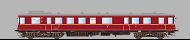
The former Deutsche Reichsbahn-Gesellschaft (DRG) ordered 50 hydraulic foru axle diesel railcars numbered as VT 137 241-270 and VT 137 442-461. The MAN diesel motors delivered 360 HP at 870 rpm and reached a maximum speed of 100 km/h. After WWII 16 railcars went to DB, seven were owned by DR.
H0 N XL L M4
- Article numbers
- 56457, 66457, 56857, 56557, 56357
- Last change
- 8/2/2016
- Manufacturer
- ESU
RhB Gmf 4/4 242-243 LokSound V4.0 European Soundfiles H0 N XL L M4
- Article numbers:56473, 66473, 56873, 56573, 56373
- Last change: 8/2/2016
- Manufacturer: ESU

For traction of trains for construction areas Swiss Rhetian Railway (RhB) ordered two diesel electric Gmf 4/4 242 and 243 at German manufacturer Kaelble-Gmeinder. The four axle locos are driven by a Caterpillar 12 cylinder prime mover 3412 DI-TA and reach a maximum speed of 60 km/h.
H0 N XL L M4
- Article numbers
- 56473, 66473, 56873, 56573, 56373
- Last change
- 8/2/2016
- Manufacturer
- ESU
BR 218 MTU 4000R 16V LokSound 5 factory equipped sounds H0 N XL L M4
- Article numbers:22401.N
- Last change: 11/15/2023
- Manufacturer: ESU

After at least 15 years of hard service, many TB11 12-cylinder 218 series diesel engines were coming to the end of their useful life. From 1996, MTU switched the production of locomotive diesel motors to the Type 4000, which was available with eight, twelve and 16 cylinders and was much more compact than the massive TB10 and TB11. In the 218, the 16-cylinder MTU 16V 4000 R40 and R41 was used for repowering, of which DB AG ordered 80 units. The engines are set for an output of 2682 hp at 1800 rpm and accelerate the 218 to 140 km/h. In contrast to the TB11 engines, the 4000 series have four small turbochargers, which, in addition to the significantly smaller displacement and the higher working speed, ensure a significantly different noise. Hide description more…
H0 N XL L M4
- Article numbers
- 22401.N
- Last change
- 11/15/2023
- Manufacturer
- ESU
License Agreement
1. GRANT OF LICENSE
1.1 ESU grants you a non-transferable, limited, non-exclusive right to use the Content solely for your own personal purposes. You may load the Content into RAM, as well as installation on a hard disk or other storage device on a single computer, hardware product or mobile device owned by you or under your control. The installation process may result in a copy of the Content residing on your computer, in which case, you may retain one (1) copy of the Content on your computer, provided that you retain all copyright and other proprietary notices on the copy and the copy is kept in your possession with the original.1.2 By using the Content, you shall not obtain any ownership, copyright, proprietary or other interest in or to the Content. The Content is licensed, not sold.
1.3 You are licensed to use, modify and combine the Sound Samples with sound samples provided by third parties, to create your own sound compositions which, subject to you complying with the terms of this Agreement, you are free to distribute as you wish provided that: (i) the Sound Samples have been mixed together to create an original work; (ii) individual Sound Samples are not used in isolation and (iii) the Sound Samples or derivatives are not used to create sound libraries for distribution to third parties.
2. PROHIBITED USES
Neither you, nor anyone at your direction, shall:2.1 use the Content, or any part of it, for any public performance, live broadcast or time delayed live broadcast where the Content is used unattended for commercial purposes without ESU' s prior written consent;
2.2 use the Content, or any part of it, in any competitive product;
2.3 sub-license, copy, reproduce, transmit, assign, rent, sell, lease, offer on a pay-per-play basis, distribute for money or any other consideration, or commercially exploit in any other manner or through any medium whatsoever or otherwise transfer in any way the Content or any part thereof;
2.4 manufacture and/or distribute for money or otherwise commercially exploit any product that incorporates any part of the Content. If you wish to use any part of the Content for manufacture, resale, sub-license or further distribution, you must contact ESU (and where relevant, its licensors) to enter into an appropriate agreement with ESU (and, where relevant, its licensors);
2.5 publish the results of any analysis or comparative evaluation of the Content or any part thereof without ESU' s prior written consent;
2.6 reverse engineer, recompile or disassemble any part of the Content except to the extent and in the circumstances expressly permitted by ESU and its licensors in writing or by law;
3. INTELLECTUAL PROPERTY RIGHTS
You acknowledge that all intellectual property rights in the Content are and shall remain vested in ESU and its licensors. You undertake not to interfere with or diminish, whether by act or omission, the rights, title and interest in the Content of ESU and its licensors. You may be held responsible by ESU and/or any of its licensors for any infringement of any intellectual property rights in the Content. For the avoidance of doubt, provided that you comply with the terms of this Agreement, ESU shall not claim ownership of the intellectual property rights in any compositions created by your use of the Content.4. TERM AND TERMINATION
This Agreement is effective from the first date you install the Content. The rights granted to you under this Agreement shall terminate if you fail to abide by its terms. Upon such termination you agree to destroy the Content including any Content stored on the hard disk of any computer under your control. You may terminate this Agreement at any time by destroying or erasing all your copies of the Content. Any termination of this Agreement (howsoever occasioned) shall not affect any accrued rights or liabilities of you or ESU nor shall it affect the coming into force or the continuance in force of the provisions of Clauses 2, 3, 5 and 6 and any provision hereof which is by implication intended to come into or continue in force on or after such termination.5. NO WARRANTIES
TO THE MAXIMUM EXTENT PERMITTED BY APPLICABLE LAW, ESU AND ITS LICENSORS PROVIDE THE CONTENT "AS IS" AND ESU EXCLUDES ON BEHALF OF ITSELF AND ITS LICENSORS, ALL CONDITIONS, TERMS, REPRESENTATIONS (OTHER THAN FRAUDULENT REPRESENTATIONS) AND WARRANTIES RELATING TO THE CONTENT, WHETHER IMPOSED BY STATUTE OR BY OPERATION OF LAW OR OTHERWISE, INCLUDING BUT NOT LIMITED TO, IMPLIED WARRANTIES OF SATISFACTORY QUALITY AND FITNESS FOR A PARTICULAR PURPOSE. NEITHER ESU NOR ITS LICENSORS WARRANT THAT THE OPERATION OF THE CONTENT WILL BE UNINTERRUPTED, ERROR FREE, VIRUS FREE OR MEET YOUR SPECIFIC REQUIREMENTS. YOU MAY HAVE OTHER RIGHTS THAT VARY FROM JURISDICTION TO JURISDICTION.6. ESU's LIABILITY
Neither ESU nor its licensors shall have any liability to you for any loss or damage caused directly or indirectly in connection with the Content, any part thereof or this Agreement, except to the extent that such liability cannot be lawfully excluded. In any case, neither ESU nor its licensors shall be liable for any loss of business, data, profits, savings, or any other special, incidental, consequential, indirect or economic loss whatsoever even if such losses were contemplated at the date of this Agreement.7. GENERAL
7.1 You acknowledge that damages alone might be insufficient remedy for any breach of the terms of this Agreement and that the remedies of injunction, specific performance or other equitable relief would be suitable remedies in the event of any breach or threatened breach of this Agreement.7.2 You may not assign or otherwise transfer all or any part of this Agreement or the rights granted to you hereunder.
7.3 ESU is not obliged to provide any maintenance, technical support or upgrades to you.
7.4 You agree to comply with all applicable import and export regulations and acknowledge that you have the responsibility for obtaining all necessary licenses to export, re-export, transfer or import the Content.
7.5 This Agreement constitutes the entire agreement between you and ESU with respect to the subject matter hereof and supersedes all prior agreements, arrangements and understandings between the parties and constitutes the entire agreement between the parties relating to such subject matter hereof. No addition to or modification of any provision of this Agreement shall be binding upon ESU and you unless made by a written instrument signed by a duly authorized representative of ESU and you.
7.6 No forbearance, delay or indulgence by either party in enforcing the provisions of this Agreement shall prejudice or restrict the rights of that party nor shall any waiver of its rights operate as a waiver of any subsequent breach and no right, power or remedy herein conferred upon or reserved for either party is exclusive of any other right, power or remedy available to that party and each such right, power or remedy shall be cumulative.
7.7 Notwithstanding that the whole or any part of any provision of this Agreement may prove to be illegal or unenforceable the other provisions of this Agreement and the remainder of the provision in question shall remain in full force and effect.
If you download the designated file, you agree to be legally bound by the license given above.