- Downloads
- Sounds
- projects.esu.eu
- Search results
BR 181 / 184 LokSound V4.0 European Soundfiles H0 N XL L M4
- Article numbers:55438, 65438, 55838, 55538, 55338
- Last change: 8/2/2016
- Manufacturer: ESU

electric locomotive DB type 181/184 for transnational operation between Germany and France
H0 N XL L M4
- Article numbers
- 55438, 65438, 55838, 55538, 55338
- Last change
- 8/2/2016
- Manufacturer
- ESU
BR 181 / 184 LokSound V4.0 & LokPilot V4.0 for Factory Equipped Locomotives H0 N XL L M4
- Article numbers:98435
- Last change: 7/24/2018
- Manufacturer: LS-Models/ESU

electric locomotive DB type 181/184 for transnational operation between Germany and France, LS-models configuration
H0 N XL L M4
- Article numbers
- 98435
- Last change
- 7/24/2018
- Manufacturer
- LS-Models/ESU
BR 181 / 184 LokSound 5 European Sound files H0 N XL L M4
- Article numbers:S0138
- Last change: 2/7/2019
- Manufacturer: ESU
electric locomotive DB type 181/184 for transnational operation between Germany and France
H0 N XL L M4
- Article numbers
- S0138
- Last change
- 2/7/2019
- Manufacturer
- ESU
ÖBB 2016 Hercules / ER20 LokSound 5 European Sound files  H0 N XL L M4
- Article numbers:S0056
- Last change: 6/27/2023
- Manufacturer: ESU

Austrian State Railways ÖBB was first Siemens customer for diesel-electric mainline diesel loco Eurorunner ER 20. Between 2002 and 2011 manufacturer delievered 181 samples to ÖBB and several european private owners. The MTU 16 V 4000 R41 develops 2000 kW and enables the loco to reach a maximum speed of 140 km/h.
F5 enables the heavy load mode: The diesel notch is always one up compared with normal operation. If you want to jump two notches, simply set CV 104 to 170 (instead of 150).
F27 turns on the manual ntoching. Once F28 is on, you can use F28 to notch up and F29 to notch down. F27, F28, and F29 must be turned off to return to normal mode. If F27 is off and you press F28, the prime mover will run to full speed.
F17 will bring the locomotive to full stop. Hide description more…
H0 N XL L M4
- Article numbers
- S0056
- Last change
- 6/27/2023
- Manufacturer
- ESU
4-12-2 Three Cylinder LokSound 5 North American and Australian Sound files H0 N XL L M4
- Article numbers:S0785
- Last change: 4/2/2024
- Manufacturer: ESU

The 4-12-2 represents the wheel arrangement of four leading wheels, twelve coupled driving wheels, and two trailing wheels. This arrangement was named the Union Pacific type, after the only railroad to use it, the Union Pacific Railroad.
Only one type of locomotive with a 4-12-2 wheel arrangement was built: the Union Pacific Railroad's 9000-series locomotives, 88 of which were built by ALCO between 1926 and 1930. These locomotives were used to increase the speed of freight trains in flat country, and were fairly successful, but were maintenance nightmares, largely because of their use of an inside third cylinder driving the cranked second driving axle between the frames. There was no inside valve gear to worry about, however. ALCO had obtained permission to use the conjugated valve gear invented by Sir Nigel Gresley. This system used two hinged levers connected to the outer cylinder's valves to operate the inner cylinder's valve. The 9000 class locomotives were the largest to use Gresley gear.
In this front view of the same locomotive the third cylinder and the mechanism that controlled it can be seen below the smokebox.
Between 1934 and 1940 eight of the first fifteen locos had their Gresley gear removed and were converted to a "double Walschaerts" valve gear which utilized a double eccentric (return) crank and second link on the right side (similar to the gear Baldwin used on its 3-cylinder experimental compound 4-10-2 #60000), which operated the valve for the inside cylinder. Union Pacific referred to this system as the "third link." The 4-12-2's constructed from 1928 utilized roller bearings in the Gresley lever bearings, thus none of these engines were converted. The pre-1928 engines not converted received the roller bearing levers in 1940, and no further conversions were made.
During design the third and fourth driving axles were planned to be "blind" (flangeless) in order to improve curve handling, but ALCO's lateral motion devices on the first and sixth axles (which allowed the axles to slide up to two inches to the side) made this unnecessary. They had the longest rigid wheelbase in North America, and the longest in the world until the Soviet Union built their 4-14-4 locomotive in 1934. The trailing truck carried the same axle load as the drivers, which was unusual.
There has been debate as to whether the first driving axle of the 4-12-2 was cranked to provide clearance for the main rod connected to the second axle. Union Pacific drawings show no such crank on the first axle, and the Railway Age article says "The 67 in (170 cm) drivers permit the use of a straight axle on the front drivers..." The spacing between the first and second axles was increased by 18 in (46 cm) to provide clearance. Based on the published dimensions, this means at its closest the centerline of the inside rod was 11.645 in (29.58 cm) from the centerline of the first axle. (UP drawings reproduced in Kratville and Bush's "Union Pacific Type" books show the inside rod 113 in (290 cm) long and the first and second driver axles 88 in (220 cm) apart. The inside cylinder axis was inclined 9.5 degrees and was 32 in (81 cm) above the plane of the driving axles at a point 181 in (460 cm) ahead of the second driving axle, so the cylinder axis missed the centerline of the second axle by 1-11/16 inches. The rod centerline is closest to the axle when the crank is 54.49 degrees below horizontal.)
There is one surviving UP 4-12-2 "Union Pacific" type locomotive. It is number 9000 displayed at the Los Angeles County Fairplex in Pomona, CA
Whistles:
CV163=0 UP 844 "Steamboat" - Default
CV163=1 Union Pacific 3-chime steamboat
CV163=2 Steam Whistle 1
CV163=3 SP 4449 Daylight
CV163=4 DRG&W 5 Chime
CV163=5 SOO Line 1003
CV163=6 DL&W 5 Chime
CV163=7 WM 6 Chime
Bells:
CV164=0 Pnuematic Bell 1
CV164=1 Pnuematic Bell 2
CV164=2 Steam Loco Rope Pull Bell
CV164=3 SOO Line 1003 Bell
CV164=4 UP 844 Air Ringer Bell - Default
CV164=5 SP 4449 Bell
CV164=6 DRG&W K27 Bell
Dynamos:
CV165=0 Soo Line 1003 Dynamo
CV165=1 K27 463 Dynamo
CV165=2 SPTriple Dynamo
CV165=3 UP Dual Dynamo
CV165=4 Z27 Dynamo
CV165=5 T16.1 Dynamo
Air Pumps
CV166=0 Cross Compound #1 Soo Line 1003
CV166=1 Cross Compound #2 K27 463
CV166=2 Cross Compound #3 SP 4449
CV166=3 Cross Compound #4UP 844
CV166=4 Single Stage #1 Z27
CV166=5 Single Stage #2 T16.1
The ESU Full Throttle Steam files now include a few new logic features for added operational realism while still leaving you in control of HOW YOU wish to run your locomotive.
Heavy Load: F9 by default.
Similar to the “Drive Hold” button on the Full Throttle Diesel files “Heavy Load” allows you to adjust the “Steam Cut Off Valve” at any speed allowing for a fierce full chuff or drifting with snifters and rod clanks. Heavy load can also act as an offset allowing speed adjustments when engaged if desired.
Coast: F4 by default.
Opposite of “Heavy Load” Coast allows for a negative offset allow drifting sounds of Rods and snifter valves at any speed. You again have the option to hold the speed to adjust the speed with this offset active. Even allowing for an increase of speed with no chuffs as if drifting downhill.
Independent brake: F10 by default
Identical to the Full Throttle Diesel files. This allows for the locomotive to stop more quickly than its regular momentum would normally carry it. This one is pretty self-explanatory – just press the brake and come to a stop! For additional options there are 3 Braking rates that can be set up for user preference.
Articulation: Sound Slot 2
By adding Sound Slot 2 to the F8 Function Mapping and enabling the "Secondary Trigger" (CV250) you can add a second set of drivers making any ESU Steam File articulated.
Function Mappable Air Horn: F21 by default
Sound Slot 21.
Many Steam locomotives had a single chime airhorn equipped. Those modelling SP, MILW, and others can now have this feature and put it where they would like in the function mapping in addition to the whistle.
S0785 - Release Notes
===================================================
V-2 R-2:
===================================================
- updated independent brake
- updated boiler hiss
V-3 R-3:
===================================================
- updated steam chuffs sound slot
V-4 R-4:
===================================================
- changed whistle sound slot 3 maximum sound slot speed to 128 Hide description more…
H0 N XL L M4
- Article numbers
- S0785
- Last change
- 4/2/2024
- Manufacturer
- ESU
Piko KM ML 4000 LokSound 5 North American & Australian factory Equipped Sound files H0 N XL L M4
- Article numbers:16460
- Last change: 4/14/2026
- Manufacturer: Piko

Piko KM ML4000 (SP9001) - 58412 LokSound 5 PluX22
In 1959, the two US railroad companies Denver & Rio Grande Western D&RGW and Southern Pacific SP each ordered three mainline diesel locomotives from the German manufacturer Krauss-Maffei. Contrary to US practice, these six-axle locomotives featured diesel-hydraulic drive technology. The two medium-speed, sixteen-cylinder Maybach MD 870 engines, equipped with exhaust gas turbochargers and intercoolers, each produced 1470 kW at 1585 rpm, the same engines already used in the pre-production locomotives of the DB Class V160. Voith L830rU transmissions, similar to those used in the production V160 locomotives, were installed. The maximum speed was 113 km/h. The two compressors for compressed air generation were US-made Gardner Denver products, driven by the diesel engines and therefore running at excessively high speeds. The fact that the locomotives, considered the most powerful single-frame diesel locomotives in the world at the time, were not destined for lasting success was due to the excessive demands of the dispatchers, who constantly sent the ML4000 out on the line at maximum load. Nevertheless, the six pre-production locomotives were followed by an order for 15 production locomotives with a completely different hood-unit design. SP retired its last Hydraulics locomotives in 1968.
This project is for the PIKO model (KM ML 4000 SP 9001) including all light functions.
These CVs were changed in the SUSI module to make the light functions work:
CV1021=2
CV983=1
CV985=0
CV987=1
CV989=0
CV1021=3
CV983=16
CV987=16
CV1000=64
CV1004=64
CV1021=4
CV982=32
CV986=32
CV1021=7
CV1001=2
CV1005=2
Horn:
F2 – Activates the air horn (5 different horns selectable with CV164 values 0-4)
CV164=0 KM ML 4000
CV164=1 Nathan P-3-R4 (Default)
CV164=2 Nathan P-3
CV164=3 Nathan P-3-R1
CV164=3 Nathan P-3-R2
Brake functions:
F16 – Dynamic braking with brake fan sound. Simulates a downhill run (speed reduction adjustable with CV181 and CV184). The locomotive significantly reduces its speed.
F17 – Brake Function 2: The locomotive brakes slowly to a standstill with brake valve sound.
Heavy Load Operation:
F29 – Activates heavy load operation. Acceleration now takes noticeably longer, and the diesel engine works harder.
Deactivate Brake Sound:
F30 – Deactivates the brake squeal when the train stops. (4 different brake sounds selectable with CV162 values 0-3)
Basis File - S0046 Hide description more…
H0 N XL L M4
- Article numbers
- 16460
- Last change
- 4/14/2026
- Manufacturer
- Piko
Pioneer Zephyr LokSound 5 North American and Australian Sound files H0 N XL L M4
- Article numbers:S0842
- Last change: 7/20/2026
- Manufacturer: ESU
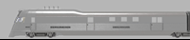
The Pioneer Zephyr is a diesel-powered trainset built by the Budd Company in 1934 for the Chicago, Burlington & Quincy Railroad (CB&Q), commonly known as the Burlington Route. The trainset was the second internal-combustion–powered streamliner built for mainline service in the United States (after the Union Pacific Railroad's M-10000), the first such train powered by a diesel engine, and the first to enter revenue service.
The trainset consists of one power/storage car, one baggage/RPO/buffet/coach car, and one coach/observation car. The cars are made of stainless steel, permanently articulated together with Jacobs bogies. The construction incorporated recent advances such as shotwelding (a specialized type of spot welding) to join the stainless steel, and unibody construction and articulation to reduce weight. It was the first of nine similarly built trainsets made for Burlington and its technologies were pivotal in the subsequent dieselization of passenger rail service.
Its operating economy, speed, and public appeal demonstrated the potential for diesel-electric-powered trains to revitalize and restore profitability to passenger rail service that had suffered a catastrophic loss of business with the Great Depression. Originally named the Burlington Zephyr during its demonstration period, it became the Pioneer Zephyr as Burlington expanded its fleet of Zephyr trainsets.
On May 26, 1934, it set a speed record for travel between Denver and Chicago when it made a 1,015.4-mile (1,633 km) non-stop "Dawn-to-Dusk" dash in 13 hours 5 minutes at an average speed of almost 78 mph (124 km/h). For one section of the run, it reached a speed of 112.5 mph (181 km/h). The historic dash inspired a film ("The Silver Streak") and the train's nickname, "The Silver Streak".
The train entered regular revenue service on November 11, between Kansas City, Missouri; Omaha, Nebraska; and Lincoln, Nebraska. It operated this and other routes until its retirement in 1960, when it was donated to Chicago's Museum of Science & Industry, where it remains on public display. The train is generally regarded as the first successful streamliner on American railroads.
Though no Pioneer Zephyr runs today, we used an 8-567C prime mover for this project.
This project is a normal idle version. It is an air throttle version. It has switcher type exhaust with a single exhaust stack.
File also contains an "Isolation Switch" Mode on F15 when Standing Still.
Pressing F15 while not moving will lower the prime mover and lock the motor. F15 must be turned off to begin moving.
Another Mode is "Reverser In Center Position". When pressing F24 while stopped, the motor will lock so you can throttle through the notches like the prototype in neutral. F24 must be turned off to begin moving.
This project has "Run 8" mode. When turning on F26 with F28 off, the prime mover goes to run 8. Turning off F26 returns the prime mover sounds back to normal mode.
This project has "Coast" mode. When turning on F27 with F28 off, the prime mover goes to idle for coasting purposes. Turning off F27 returns the prime mover sounds back to normal mode.
You can still use F26 and F27 for manual notching. You have to keep both F26 and F27 off before pressing F28 to turn on manual notching. Once F28 is on, you can use F26 to notch up and F27 to notch down. F26, F27, and F28 must be turned off to return to normal mode.
This project has "Load" mode. When turning on F29 with F15, F24, F26, F27, F28 off, the prime mover goes into load mode. While you are using load mode, the prime mover will notch up 1 or more notches based on primary load settings(CV104). The throttle notches up using speed instead of requested speed while using the load feature. F29 must be turned off to return to normal mode.
Prime mover volume selection mode. By default the prime mover has volume dynamics. Meaning idle is soft while notch 8 is loud. This is very prototypical. The next option is volume maxed out. Meaning idle and notch 8 are the same volume. This is more suitable for people who like it loud.
Change the sound configuration of the prime mover sound slot 1
CV31 = 16, CV32 = 1
----------------------
CV263 = 0 Prime Mover Dynamic Volume Control
CV263 = 1 Prime Mover Max Volume
Pioneer Zephyr Horn Pack 1
Horns (SoundCV9):
CV163=0 Leslie A-200 + Leslie A-125 Horn Combo
CV163=1 Leslie A-200 + Leslie A-125 Horn Combo Ed2
CV163=2 Leslie A-200
CV163=3 Leslie A-125
CV163=4 Leslie A-200 Ed2
CV163=5 Leslie A-125 Ed2
CV163=6 Leslie A-75 Ed2
CV163=7 Wabco E-2
CV163=8 Wabco E-2 Ed2
CV163=9 Hancock 4700 Whistle
CV163=10 Hancock 4700 Whistle Ed2
CV163=11 Nathan MS-1
CV163=12 Nathan M-5
CV163=13 Nathan M-3
CV163=14 Leslie A-75
Pioneer Zephyr Bell Template Pack 1
Bells (SoundCV10):
CV164=0 Pioneer Zephyr Air Bell 001
Auto Bell:
Many Second and Third Generation locomotives have been fitted with an Automatic Bell that is triggered when the horn is blown. In MANY cases this cannot even be bypassed on modern locos. Before the FRA mandated this feature on new locomotives the bell was of course turned on and off separately. Some locomotives were delivered with a manual bell and have been converted to an automatic bell. This creates a challenge in sound file creation.
We realize that not every loco with a particular prime mover had this feature. As such we have built in an option to turn the feature on and off. We will set the default in the file to be what is most appropriate for the particular file.
To turn the feature OFF - Auto Bell OFF:
1. Remove the Auto bell sound slot from the function mapping chart
CV31 = 16, CV32 = 8
----------------------
CV311 = 4
2. Change the sound configuration of the Auto bell sound slot
CV31 = 16, CV32 = 1
----------------------
CV287 = 0
To turn the feature ON - Auto Bell ON:
1. ADD the Auto bell sound slot from the function mapping chart
CV31 = 16, CV32 = 8
----------------------
CV311 = 12
2. Change the sound configuration of the Auto bell sound slot
CV31 = 16, CV32 = 1
----------------------
CV287 = 1
Auto Bell Timer:
The Bell timer is amount of time the bell will play after the horn if the auto timer is active. The timer is broken down into 1/4 of a second increments.
CV169=4 - 1 Second
CV169=8 - 2 Seconds
CV169=12 - 3 Seconds
CV169=16 - 4 Seconds
CV169=20 - 5 Seconds - Default
Etc...
1st Generation Brake Squeal Template Pack 1
Brake Squeal (SoundCV11)
CV165=0 Composition Shoe #1
CV165=1 Cast Iron Shoe #1
EMD 1st Generation Switcher Air Dryer Template Pack 1
Air Dryer (SoundCV12)
CV166=0 NW2 Air Dryer 1
CV166=1 NW5 Air Dryer 1
CV166=2 SW7 Air Dryer 1
CV166=3 SW10 Air Dryer 1
S0842 - Release Notes
===================================================
V-1 R-1:
===================================================
- new project
V-2 R-2:
===================================================
- bell update Hide description more…
H0 N XL L M4
- Article numbers
- S0842
- Last change
- 7/20/2026
- Manufacturer
- ESU
License Agreement
1. GRANT OF LICENSE
1.1 ESU grants you a non-transferable, limited, non-exclusive right to use the Content solely for your own personal purposes. You may load the Content into RAM, as well as installation on a hard disk or other storage device on a single computer, hardware product or mobile device owned by you or under your control. The installation process may result in a copy of the Content residing on your computer, in which case, you may retain one (1) copy of the Content on your computer, provided that you retain all copyright and other proprietary notices on the copy and the copy is kept in your possession with the original.1.2 By using the Content, you shall not obtain any ownership, copyright, proprietary or other interest in or to the Content. The Content is licensed, not sold.
1.3 You are licensed to use, modify and combine the Sound Samples with sound samples provided by third parties, to create your own sound compositions which, subject to you complying with the terms of this Agreement, you are free to distribute as you wish provided that: (i) the Sound Samples have been mixed together to create an original work; (ii) individual Sound Samples are not used in isolation and (iii) the Sound Samples or derivatives are not used to create sound libraries for distribution to third parties.
2. PROHIBITED USES
Neither you, nor anyone at your direction, shall:2.1 use the Content, or any part of it, for any public performance, live broadcast or time delayed live broadcast where the Content is used unattended for commercial purposes without ESU' s prior written consent;
2.2 use the Content, or any part of it, in any competitive product;
2.3 sub-license, copy, reproduce, transmit, assign, rent, sell, lease, offer on a pay-per-play basis, distribute for money or any other consideration, or commercially exploit in any other manner or through any medium whatsoever or otherwise transfer in any way the Content or any part thereof;
2.4 manufacture and/or distribute for money or otherwise commercially exploit any product that incorporates any part of the Content. If you wish to use any part of the Content for manufacture, resale, sub-license or further distribution, you must contact ESU (and where relevant, its licensors) to enter into an appropriate agreement with ESU (and, where relevant, its licensors);
2.5 publish the results of any analysis or comparative evaluation of the Content or any part thereof without ESU' s prior written consent;
2.6 reverse engineer, recompile or disassemble any part of the Content except to the extent and in the circumstances expressly permitted by ESU and its licensors in writing or by law;
3. INTELLECTUAL PROPERTY RIGHTS
You acknowledge that all intellectual property rights in the Content are and shall remain vested in ESU and its licensors. You undertake not to interfere with or diminish, whether by act or omission, the rights, title and interest in the Content of ESU and its licensors. You may be held responsible by ESU and/or any of its licensors for any infringement of any intellectual property rights in the Content. For the avoidance of doubt, provided that you comply with the terms of this Agreement, ESU shall not claim ownership of the intellectual property rights in any compositions created by your use of the Content.4. TERM AND TERMINATION
This Agreement is effective from the first date you install the Content. The rights granted to you under this Agreement shall terminate if you fail to abide by its terms. Upon such termination you agree to destroy the Content including any Content stored on the hard disk of any computer under your control. You may terminate this Agreement at any time by destroying or erasing all your copies of the Content. Any termination of this Agreement (howsoever occasioned) shall not affect any accrued rights or liabilities of you or ESU nor shall it affect the coming into force or the continuance in force of the provisions of Clauses 2, 3, 5 and 6 and any provision hereof which is by implication intended to come into or continue in force on or after such termination.5. NO WARRANTIES
TO THE MAXIMUM EXTENT PERMITTED BY APPLICABLE LAW, ESU AND ITS LICENSORS PROVIDE THE CONTENT "AS IS" AND ESU EXCLUDES ON BEHALF OF ITSELF AND ITS LICENSORS, ALL CONDITIONS, TERMS, REPRESENTATIONS (OTHER THAN FRAUDULENT REPRESENTATIONS) AND WARRANTIES RELATING TO THE CONTENT, WHETHER IMPOSED BY STATUTE OR BY OPERATION OF LAW OR OTHERWISE, INCLUDING BUT NOT LIMITED TO, IMPLIED WARRANTIES OF SATISFACTORY QUALITY AND FITNESS FOR A PARTICULAR PURPOSE. NEITHER ESU NOR ITS LICENSORS WARRANT THAT THE OPERATION OF THE CONTENT WILL BE UNINTERRUPTED, ERROR FREE, VIRUS FREE OR MEET YOUR SPECIFIC REQUIREMENTS. YOU MAY HAVE OTHER RIGHTS THAT VARY FROM JURISDICTION TO JURISDICTION.6. ESU's LIABILITY
Neither ESU nor its licensors shall have any liability to you for any loss or damage caused directly or indirectly in connection with the Content, any part thereof or this Agreement, except to the extent that such liability cannot be lawfully excluded. In any case, neither ESU nor its licensors shall be liable for any loss of business, data, profits, savings, or any other special, incidental, consequential, indirect or economic loss whatsoever even if such losses were contemplated at the date of this Agreement.7. GENERAL
7.1 You acknowledge that damages alone might be insufficient remedy for any breach of the terms of this Agreement and that the remedies of injunction, specific performance or other equitable relief would be suitable remedies in the event of any breach or threatened breach of this Agreement.7.2 You may not assign or otherwise transfer all or any part of this Agreement or the rights granted to you hereunder.
7.3 ESU is not obliged to provide any maintenance, technical support or upgrades to you.
7.4 You agree to comply with all applicable import and export regulations and acknowledge that you have the responsibility for obtaining all necessary licenses to export, re-export, transfer or import the Content.
7.5 This Agreement constitutes the entire agreement between you and ESU with respect to the subject matter hereof and supersedes all prior agreements, arrangements and understandings between the parties and constitutes the entire agreement between the parties relating to such subject matter hereof. No addition to or modification of any provision of this Agreement shall be binding upon ESU and you unless made by a written instrument signed by a duly authorized representative of ESU and you.
7.6 No forbearance, delay or indulgence by either party in enforcing the provisions of this Agreement shall prejudice or restrict the rights of that party nor shall any waiver of its rights operate as a waiver of any subsequent breach and no right, power or remedy herein conferred upon or reserved for either party is exclusive of any other right, power or remedy available to that party and each such right, power or remedy shall be cumulative.
7.7 Notwithstanding that the whole or any part of any provision of this Agreement may prove to be illegal or unenforceable the other provisions of this Agreement and the remainder of the provision in question shall remain in full force and effect.
If you download the designated file, you agree to be legally bound by the license given above.